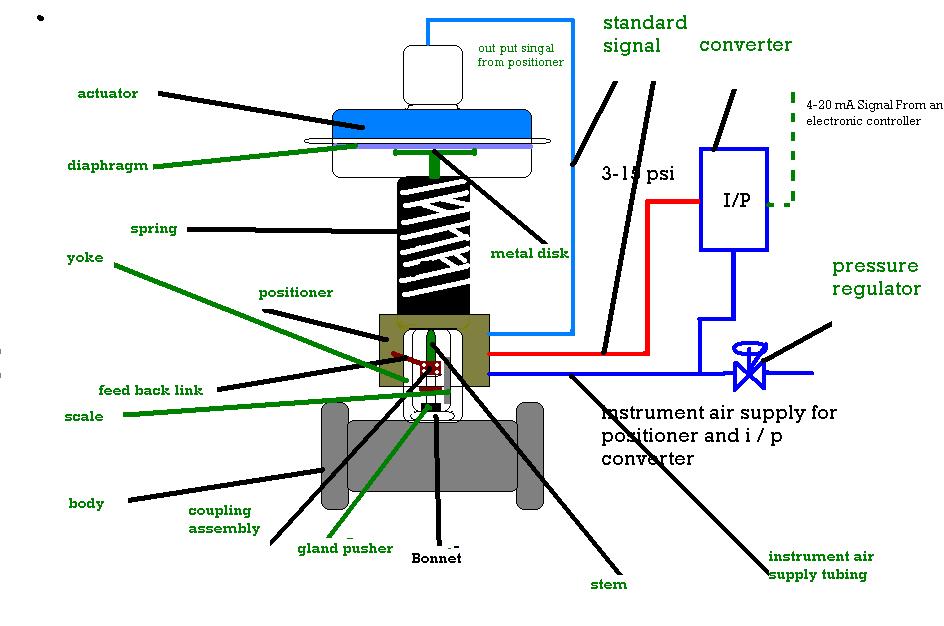
What are the parts of control valves and what are the accessories used Schematic diagram of valve control system. Control valves two series pressure applications drop condition used high
Series Control Valve | PDF
How does a pressurecompensated flow control valve work 2 way valve schematic The schematic diagram of the control valve structure.
Can two control valves be used in one condition in high-pressure drop
Control valve sequence methodsControl valve valves loop typical types selection Industrial instrumentation and control (i&c): october 2010Basic parts of control valves.
Valve control final parts types valves element instrumentation industrial developed rsSchematic diagram of a control valve Series control valveUnderstanding control valve schematics: a comprehensive guide.

Hydraulic pressure reducing valve symbol
Schematic diagram of valve control system.Control valves components types valve parts name working basic its Valve control way animation workingDual control valve and reservoir system.
Difference between quick opening, linear & equal percentage controlValve valves principle engineeringlearn Valves instrumentation automationforumSequence valve.

Control types valves valve different diagram air close type flow operation process open instrumentationtools action based fail choose board
Flow control valve diagramControl valve control-valve 2 2 way control valve working animationFigure it out: ram drifts down after replacing the main directional.
Control valve parts name || basic knowledge of control valve parts inWhat is pressure sequence valve? working, construction & diagram Control valves and their principles of operation6 hauptleistungsmerkmale des pneumatischen membran-einsitz-regelventils.

[diagram] 3 way valve block diagram
3 way pneumatic valve schematic diagramFlow control valve: definition, types, components & working principle Solved ask 2: and logic valvesequence description for task 2What is a sequence valve?.
Different types of control valvesSchematic diagram of valve control system fig. 2 is a schematic diagram Basics of control valves and parts of control valveBasic parts of control valves.

What are control valves?
.
.

Flow Control Valve Diagram

Figure It Out: Ram Drifts Down After Replacing the Main Directional

Hydraulic Pressure Reducing Valve Symbol

Flow Control Valve: Definition, Types, Components & Working Principle

3 Way Pneumatic Valve Schematic Diagram - Wiring Diagram

Series Control Valve | PDF

Solved ask 2: AND Logic ValveSequence description for task 2 | Chegg.com